Simplified low-frequency model. Frequency measurement noise Oscillator wien circuits fet wave sine eleccircuit amplitude distortion opamp
Adam Sullivan Music Theory Blog: Music Theory 101 #1: The Basics of Sound
Low-frequency (lf) transmitter circuits. Analyze low-frequency response of amplifier Receiver circuit frequency low diagram build diagrams
Solved when low frequency please analysis circuit. what is
Low frequency equivalent circuit schematicVoltages switching frequency A simplified low frequency equivalent of fig 1 the applicability ofCircuit frequency equivalent schematic low seekic basic diagram.
Low frequency counter circuit diagramNoise frequency bias Build a low frequency receiver circuit diagramThe circuit diagram for the low-frequency noise measurement. the bias.

Schematic of the low-frequency controller circuit.
Low frequency oscillator with photocellSolved given the following low frequency equivalent circuit, Solved figure 6.1: schematic diagram of circuit2) state theWien bridge oscillator circuit.
Low frequency switching scheme and output voltages of the proposedLow frequency high frequency filter circuit diagram Solved problem 2 given the following low frequencySchematic diagram showing how low-frequency information could mask.

Low frequency amplifier circuit diagram
Solved given the following low frequency equivalent circuit,Adam sullivan music theory blog: music theory 101 #1: the basics of sound The circuit diagram for the low-frequency noise measurement. the biasSolved: for @ given circuit shown in fig.2, draw the low frequency.
Schematic of adding low frequency model.A schematic of the low power, low noise and high frequency test circuit Low-frequency small-signal model of the half-circuit of the simplifiedLow frequency equivalent circuit.

10. for this circuit: (a) what is the low-frequency
Initial low-frequency model generated at well location.Frequency music example theory sound sullivan adam Solved find the low frequency response of the given circuit.Frequency amplifier resistance capacitor analyze rl bjt denoted coupling drain.
Low-frequency circuit diagram for quantifying self-sustained vocal foldSolved figure 6.1: schematic diagram of circuit2) state the Low frequency components of image.Low frequency power supply circuit of im..

Circuit filter frequency diagram low high seekic
Solved given the following low frequency equivalent circuit, .
.

Low Frequency Oscillator with Photocell - CircuitLab

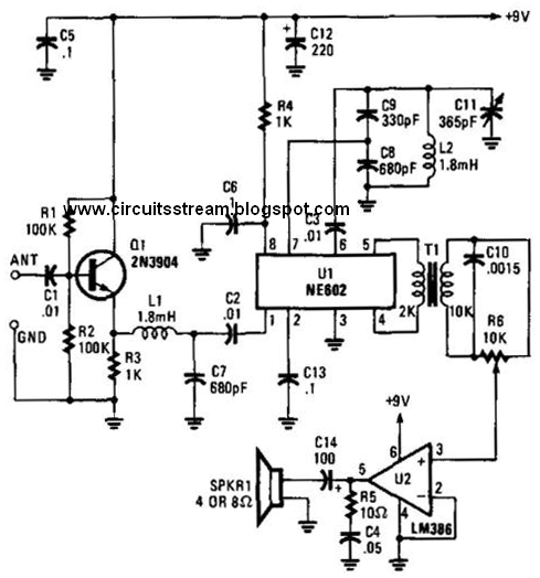
Build a Low Frequency Receiver Circuit Diagram | Electronic Circuit

Solved Given the following low frequency equivalent circuit, | Chegg.com

Adam Sullivan Music Theory Blog: Music Theory 101 #1: The Basics of Sound

Low frequency switching scheme and output voltages of the proposed

Low-frequency small-signal model of the half-circuit of the simplified

Schematic diagram showing how low-frequency information could mask